Formula 1 Technology
The engineering explained
- In stock, ready to ship
- Inventory on the way
CHAPTER 14
Cockpit controls
F1 car cockpits have changed dramatically since the relatively simple layout used in the early days of the sport, and the cars’ controls remained relatively minimalist until the early 1980s. Other than the obvious mechanical controls (pedals, steering wheel and in later years mechanical brake-bias and anti-roll-bar adjusters), and a rudimentary instrument panel, the driver did not need any other controls.
By contrast, the systems on a modern F1 car are extremely complex to operate, and as well as ‘simply’ driving the car — steering, accelerating, changing gear, braking, and keeping an eye on the position of other cars on the track — the driver constantly has to monitor and adjust a range of systems designed to optimise the performance of the car. This level of multi-tasking is probably on a par with that required by a military jet pilot, and so to ease the driver’s workload the controls in the cockpit must be designed to be as intuitive to operate and as accessible as possible.
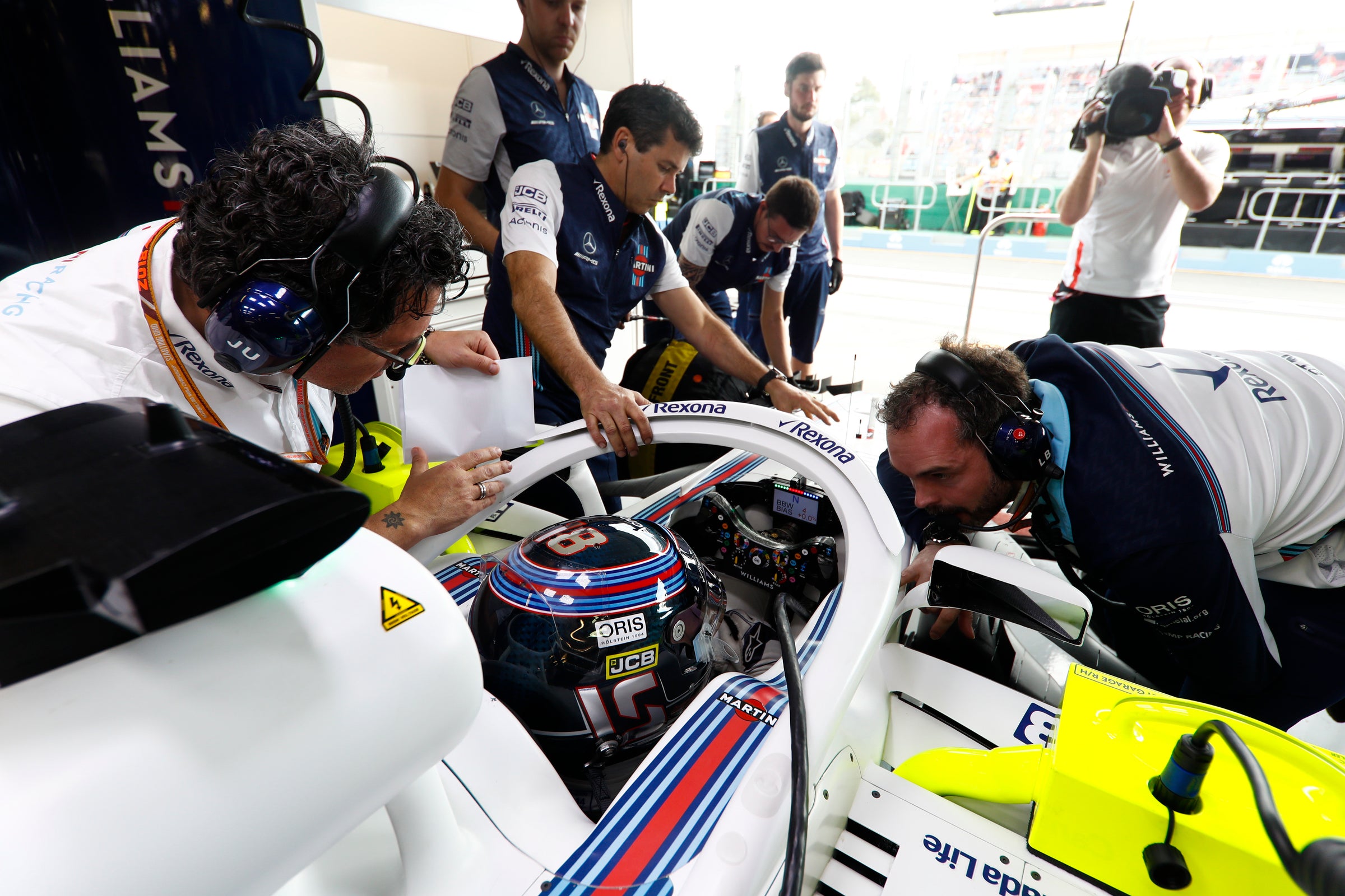
Since the late 1990s, most of the important controls that require frequent use during a race are mounted on the steering wheel. Although the control layout can be tailored to suit each driver’s preferences, the team aims to keep the controls common to both cars wherever possible in order to avoid confusion for the engineers and mechanics working on both cars.
A driver will often have his own preferences for the layout of the car’s controls, and this is an important part of making a driver feel comfortable in the cockpit.
Cockpit display
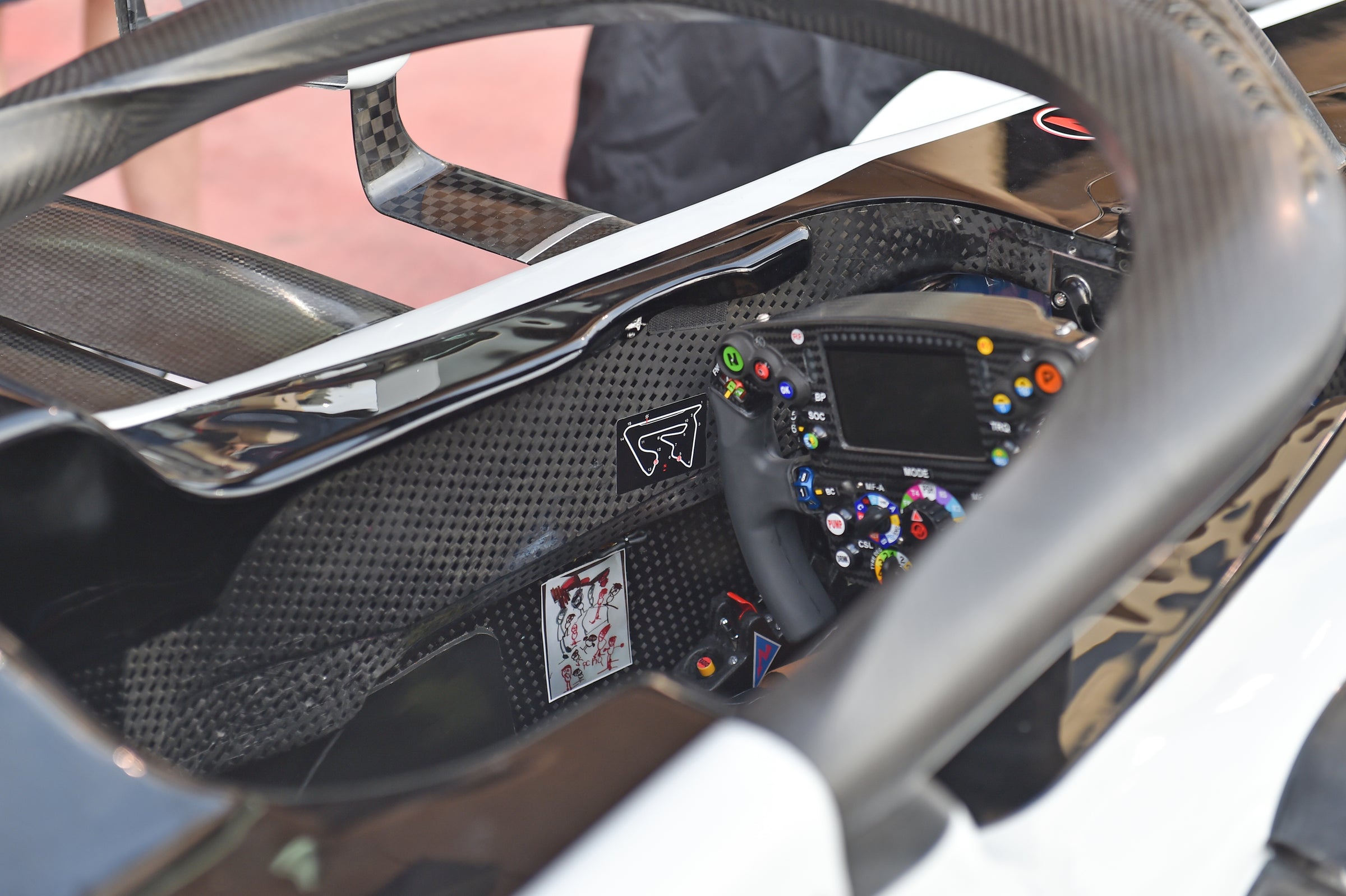
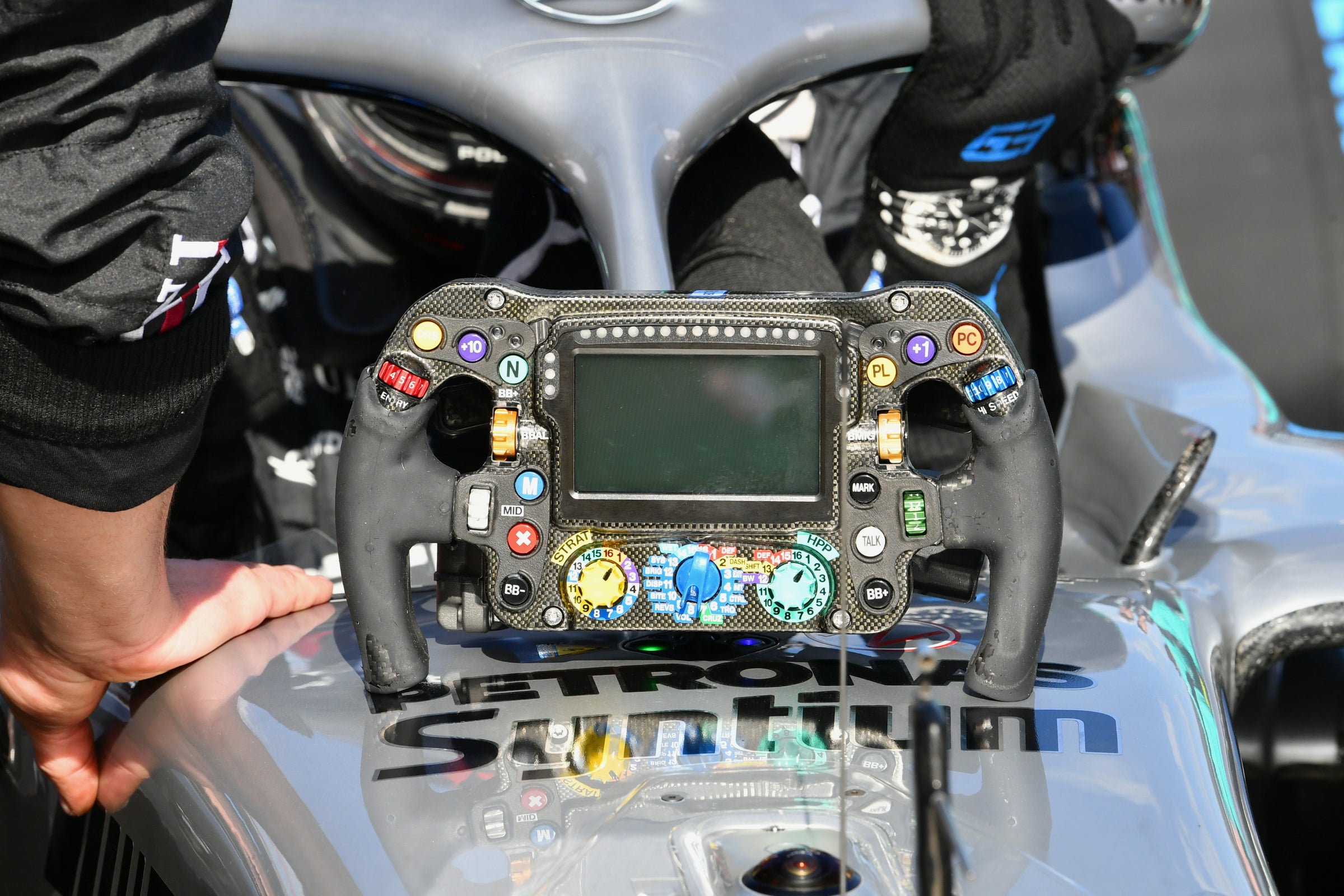
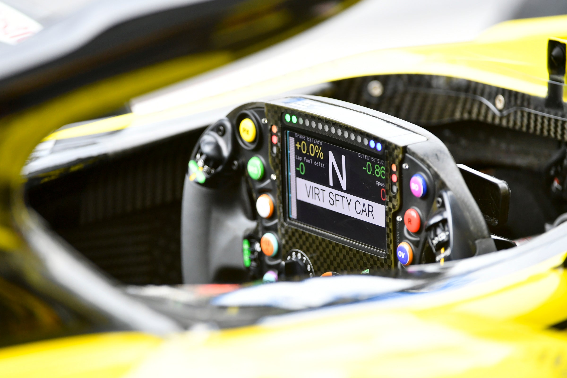
Since 2014, all cars on the grid have used a multi-function LCD display supplied by McLaren Applied Technologies — the PCU-8E for 2022. In most cases, the display is mounted on the steering wheel, although Williams has continued to buck the trend in recent years by mounting the display on the car’s dashboard.
The module receives signals from various systems via the FIA Standard ECU and the cars CAN Bus system (see Chapter 11), and the driver can select the data displayed on the screen, with the ability to toggle between data such as engine revs, engine temperatures and pressures, gear selected and lap and sector times, etc.
A series of gearchange indicator lights above the main display is used to inform the driver of the optimum point to change into a higher gear, with, from the left of the display, five green, five red and then five blue LED lights. These lights are important to ensure that the driver gets the best from the engine, although some teams also use an acoustic indicator to denote the optimum shift points.
In addition, the main cockpit display incorporates red, yellow and blue LED lights on either side of the display, operated by the FIA Marshalling System (see Chapter 11) to mirror the trackside marshalling signals.
The display unit features a backlit 4.3in LCD display with adjustable brightness. The information and alarm text messages displayed on the screen are fully customisable, with 16 different gauge types for displaying data, including a bargraph tachometer, and each team can set its own configuration using a PC, via a USB connection and configuration software. A total of 100 pages of information are available, although not all are necessarily used, and some are used for information relevant to the engineers and mechanics, rather than the driver.
Steering wheel
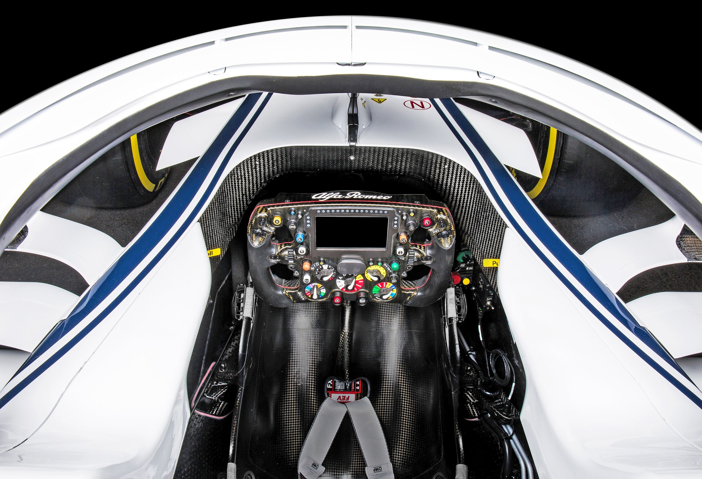
The steering wheel is one of the most important components on the car. As well as performing its obvious function as the interface between the driver and his car, providing him with feedback from the steering and front suspension, the steering wheel also acts as the platform for many of the car’s main controls.
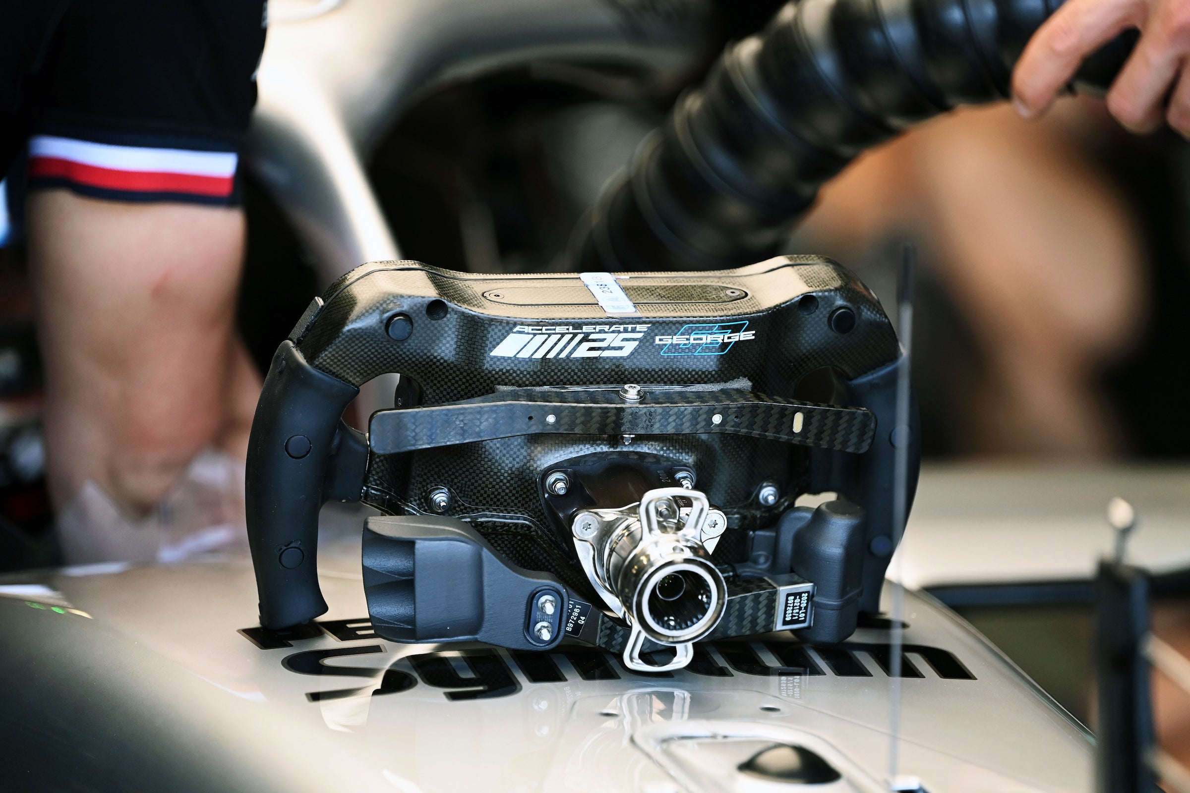
The steering wheel is made from carbon-fibre, and contains a built-in electronic control unit (ECU) to provide electrical feeds to the various systems controlled by the switchgear mounted on it. A multi-pin electrical connector provides the connection to the car, and pins in the back of the steering wheel engage with a connector in the centre of the steering column when the wheel is pushed into place.
The wheel is fitted with a quick-release mechanism to allow the driver to remove and refit it easily. This is necessary because the steering wheel must be removed to allow the driver to get in and out of the car. The wheel locks into place on the end of the steering column, and the quick-release mechanism is operated by a collar, located behind the centre hub of the wheel, which the driver pulls towards him to release the wheel. To refit the wheel, the driver simply pushes the wheel into position on the mounting hub until the locking mechanism secures it in position.
The steering wheel must be fitted to the column during the FIA steering column impact test, and the impact load used during the test is applied to the centre of the steering wheel, in line with the axis of the steering column. The quick-release mechanism must still function normally following the test.
Because the steering on an F1 car is extremely sensitive, and the lock-to-lock range is only around three-quarters of a turn at most circuits, there is no need for the steering wheel to be circular, and so the wheel is shaped more like an aircraft control yoke, with two grips and cutaway upper and lower sections. The rubber handgrips are usually a bespoke shape for a specific driver.
Within each team, the layout of the controls on the steering wheel is generally kept as similar as possible for each driver, to ease manufacture and to reduce the scope for confusion among the mechanics and engineering staff, but the various buttons and controls are tailored for each driver’s preferences. Ergonomics are very important in order for the driver to be able to find relevant controls and make the appropriate adjustments while driving the car, and the systems that require frequent adjustment have controls that are easily accessible on the wheel, with buttons that can be accessed without the need for the driver to change the position of his hands on the wheel.
The layout of the controls on the steering wheel varies significantly from team to team, as does the function of the various controls, and the descriptions of their functions. Needless to say, teams are reluctant to shout too loudly about any specific control systems that may provide them with an advantage!
Typically, the steering wheel includes the following controls (accessible via buttons, thumbwheels and multi-position rotary switches):
- Team radio
- Pitlane speed limiter
- DRS operation
- Overtake (energy deployment)
- Neutral
- Race start (maximum power, etc, for race start)
- Corner entry, mid-corner, high-speed and corner-exit differential settings
- Brake-by-wire mapping
- Brake balance (+/-)
- Customisable buttons and paddles for significant track-specific adjustments
- Fail mode controls
- Recharge (ERS — for instance before a qualifying lap)
- Driver default adjustment buttons (used for resetting sensors, etc)
- Power-unit controls (boost, energy recovery, etc)
- Gearshift paddles
- Clutch paddle(s)
- ‘Spare’ buttons and sometimes paddles for assignment to track- and driver-specific ‘shortcut’ control settings
All cars have two paddles at the back of the steering wheel for gearshifts — generally one for upshifts and one for downshifts, though the way in which they operate can be tailored to the driver’s preferences.
Either a single clutch paddle, or two clutch paddles may also be fitted, depending on team and driver preferences. The positioning and operation of the clutch paddle(s) is closely regulated by the FIA to prevent the clutch paddle(s) being used to simultaneously or sequentially operate any other devices or controls on the car. The regulations stipulate that the clutch paddle(s) must be operated only by pulling towards the driver.
Pedals
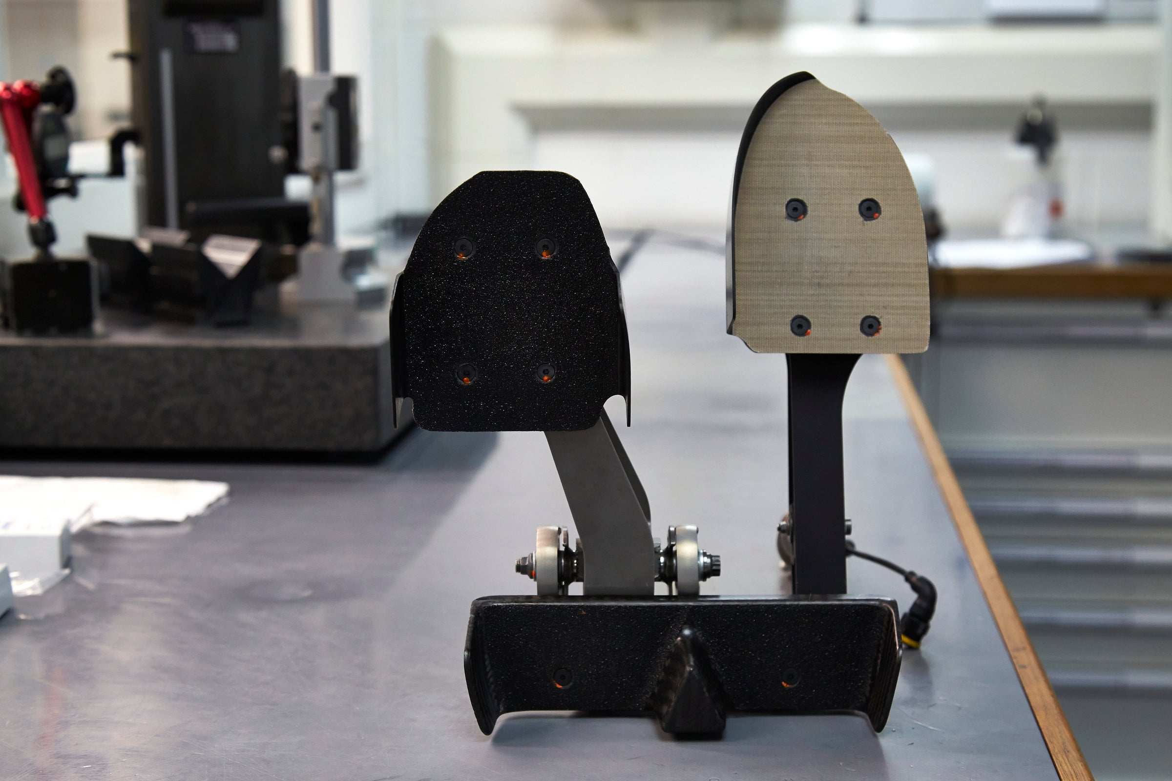
Only two pedals are fitted to an F1 car — the throttle pedal and the brake pedal. As previously explained, the clutch is operated via a paddle on the steering wheel.
The driver brakes with his left foot and uses his right foot for the throttle — he cannot move his feet between the pedals, as there is insufficient space, and the steering column runs between his feet.
On bumpy circuits, each pedal is fitted with a ‘fence’ around its edge to prevent the driver’s foot from slipping off, although operating the pedals on a bumpy circuit can still be a challenge. As with the other controls on the car, the pedal positions can be adjusted to suit driver preference, and the pedal pads are bespoke for each driver.
The brake pedal operates separate master cylinders for the front and rear brake hydraulic circuits in the conventional way (although the rear master cylinder operates a pressure sensor used to supply a signal to the brake-by-wire system, rather than operating the rear brakes directly using hydraulic pressure — see Chapter 6). There is no physical connection between the throttle pedal and the throttle mechanism on the engine — the throttle pedal operates a position sensor which then provides signals to the FIA Standard ECU to operate the throttle via a hydraulic actuator.
Other cockpit-mounted controls
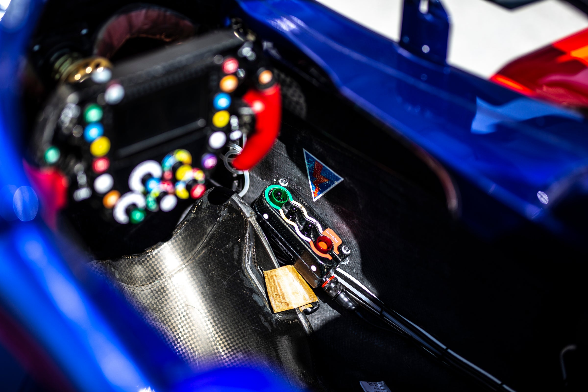
The only other controls mounted in the cockpit and operated by the driver are the ignition switches and the fire extinguisher/electrical cut-off switch.
Ignition switches
In most cases, a separate switch (‘auxiliary’ switch) is fitted to energise the car’s systems with the exception of the engine. A second switch is usually fitted to activate the ignition system for the internal combustion engine, which is operated when the engine is about to be started using the remote starter.
Fire extinguisher/electrical cut-off switch
A combined fire extinguisher/electrical cut-off switch is fitted in the cockpit for use by the driver in an emergency. This switch is described in more detail in Chapter 13
• Chassis: design and manufacture; survival cell, fuel tank, impact structures, stiffness.
• Aerodynamics: principles, front and rear wings, turning vanes, sidepods, floor, wheels and their effect, brake ducts, suspension components, diffuser, Drag Reduction System (DRS).
• Suspension, steering and brakes: suspension layout, geometry and adjustments; steering wheel, column and geometry; brake hydraulics, brake-by-wire system, discs, calipers, pads and cooling.
• Power unit: the hybrid era, Internal Combustion Engine (ICE), Energy Recovery System (ERS), fuel.
• Transmission: clutch, gearbox, differential, driveshafts.
• Electronics: starting system, Electronic Control Unit (ECU), sensors, radio and data communications, cockpit display, cameras.
• And more: wheels and tyres; hydraulic system; safety equipment; cockpit controls.
• Chapters about car design and set-up.
• Use of analysis and simulation techniques such as computational fluid dynamics (CFD), wind-tunnel testing and rig testing.
Format: 272x228mm
Hardback
Page extent: 332pp
Illustration: 450 illustrations
We deliver to addresses throughout the world.
UK Mainland delivery costs (under 2kg) by Royal Mail £5.00.
Books will normally be shipped within two working days of order. Estimated delivery times post shipment. UK: Up to 5 working days. Europe, Northern Ireland and Highlands and Islands: Up to 8 days. USA: Up to 12 days
IMPORTANT NOTICE FOR EU CUSTOMERS: Delivered Duty Unpaid (DDU) means that customers are responsible for paying the destination country's customs charges, duties. Regrettably parcels will sometimes be held by customs until any outstanding payments are made. Any payments not received may result in courier returning or in some cases destroying your books.
Unwanted products can be returned with the original packaging within 14 days of delivery. Returns will be at your own cost.
If you receive a faulty or damaged item please contact orders@evropublishing.com for return and replacement information.


